Introduction
Known relationships:
- Higher voltages allow the same output with a lower current and thus permit smaller copper cross-sections for cables and connectors. This relationship is linear and continuous.
- However, higher voltages also require enhanced insulation measures as well as air and creepage distances. From a scientific point of view, this relationship is continuous, but in technical implementation, it is divided into classes due to standards and regulations.
Realization: For an economically optimum calculation and dimensioning, select the technically practical voltage class first and then perform calculation and dimensioning near the upper limit. In practical implementation, this requires a few considerations that will be briefly discussed in this white paper.
Table of contents
- 1 A few basics
- 1.1 Real power, apparent power CosPhi
- 1.2 Rotating field generation for motors with inverters
- 1.3 Voltage generation in an inverter with PWM
- 2 Specific calculation and dimensioning for voltages
1 A few basics
1.1 Real power, apparent power CosPhi
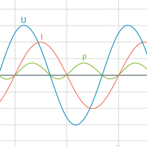
The electrical real power, for example, of drives, is the product of voltage, current, and the cosine of the angle between voltage and current, the socalled cos phi. With ohmic resistances, cos phi = 1. With ideal inductances or capacitors, cos phi = 0. The proportion of the power in which voltage and current run at an offset of exactly 90 degrees is called the reactive power. A mixture of both of these is the apparent power (s. fig. 1).
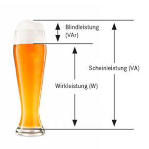
Electric drives, in other words, electric motors, have a behavior that is somewhere between ohmic and inductive. The effective cos phi of electric motors is due to their electromagnetic design and can also be influenced by the inverters. Typical values range from 0.75 to 0.9.(s. fig. 2).
Conclusion: Knowledge of the actual cos phi of a driven electric motor is important for calculating and dimensioning conductors and inverters The higher apparent power must be generated and transmitted, not just the real power of the motor.
Efficiency: The cos phi of the motor only indicates the proportion of the real power. This, however, consists of the mechanical power and the thermal power (friction and electric heat output of different sources in the motor).
Relationship: Mechanical power = apparent power * cos phi * efficiency
The apparent power is the electrical power at the motor terminals or the inverter output.
1.2 Rotating field generation for motors with inverters
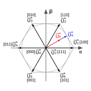
Rotating fields for the rotary motion of electric motors can be mechanically generated by brushes or, in a first approximation, brushlessly and wear-free with an electrical rotating field using inverters. Three-phase rotating fields are the most common ones. The most common three-phase rotating fields are inverters with six „switches“ (here usually IGBT).
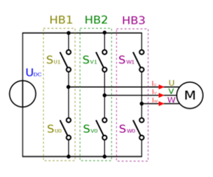
The switches SU1 and SU0 , for example, can set phase U either to the upper voltage level UDC or to the lower one with 0 V. In the switch position [100], the voltage accordingly points in the direction of +U1, in other words, horizontally to the right. If the connection is only digital, a rotary motion in six steps or blocks results. This is also referred to as block commutation.
1.3 Voltage generation in an inverter with PWM
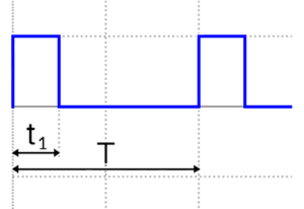
If the inductance present in the motor windings is utilized, the „switches“ of the inverter can also be clocked with a suitably high frequency. This is also referred to as modulation. Let‘s take another look at the switches SU1 and SU0, here in interaction. The voltage at terminal U is UDC when switch SU1 is on and SU0 is off at the same time. The voltage is ZERO when SU1 is off and SU0 is on at the same time. In the figure, 25% is on and 75% is off. Averaged over time, the effective voltage at terminal U would be 25% of UDC.
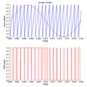
Application: Applying such a PWM method to all three phases produces a 3-phase rotating field with an almost sinusoidal curve of the average voltage at the motor terminals. This is referred to as sine commutation.
Maximum output voltage at inverters: If the upper and lower switches are both switched „on“ at the same time, then destructive short-circuit currents will flow. Consequently, this must be prevented. As a result of switching times and switching curves, inverters therefore have a so-called locking time for which both switches are „off“ between two switching statuses. This time is naturally „lost“ for generating voltage at the motor terminal. Losses that occur in the switches themselves must also be deducted.
ARADEX advantage: Higher possible output voltage
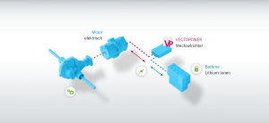
VECTODRIVE inverters and the VECTOPOWER mobile inverter have a higher-than-usual maximum output voltage with an otherwise identical DC voltage, for example, from a battery or a DC link. This is because their FPGA technology and in-house driver stages keep the technically required locking times considerably shorter.
With a 750 V DC and 4 kHz PWM cycle, this advantage is around 10-15 V.
With a 750 V DC and 8 kHz PWM cycle, the advantage is around 20-30 V.
(Comparison of a locking time of 1.6 μs instead of the market standard 4 μs.)
2 Specific calculation and dimensioning for voltages
The following is clear: At all operating points of an electric motor, it must be ensured that the inverter can provide at least the voltage that the motor needs at its terminals. The voltage of an electric motor at a particular operating point of torque and speed can be determined by the calculation and dimensioning of the winding. Calculation and dimensioning for higher terminal voltages with the same speed generate the same torque with correspondingly low phase currents.
Dimensioning and calculation of the motor for voltage: In the case of a volatile DC link voltage, the motor must be calculated and dimensioned for the lowest occurring DC voltage. During operation with higher DC voltages, the inverter controls this through less modulation. This decreases its efficiency, however, and the ripple current increases in the motor.
Calculation and dimensioning of inverter, conductors, and terminals: These components must be calculated and dimensioned for the highest occurring DC voltage as well as the maximum current that results from the previous calculation and dimensioning of the motor.
Increasing the DC link voltage: If only the DC link voltage is increased, without a corresponding adjustment of the motor winding as well, the available motor power will decrease even with the same inverter. Example of a traction motor on a VECTOPOWER traction inverter: Operation either with 600 V DC or 750 V DC. Motor winding with different dimensioning:
| UZK | P Motor1 (410 VAC) rel. | P Motor2 (512 VAC) rel. |
|---|---|---|
| 600 VDC | 100% | no function |
| 750 VDC | 91,7% | 114,5% |
If the DC voltage and motor terminal voltage are set high, the same inverter can generate around 14.5% higher outputs. If the DC voltage is set high but the motor is left at the lower voltage, over 8% of the inverter power is lost. (This is caused by higher switching losses with a higher DC voltage).
Conclusion: The most efficient way to calculate and dimension the motor, inverter, and terminals as well as to limit the overall cost is to calculate and dimension the motor windings so that the terminal voltage is near the calculation and dimensioning limit of the DC link at maximum speed.
Variations in the DC link
If there are volatile DC voltages in the DC link, the motor must be dimensioned for the lowest voltage, and the inverter, conductors, terminals, etc. must be dimensioned for the corresponding currents and the highest occurring voltages. The greater the fluctuation range of the voltage in the DC link must be assumed, the higher the overdimensioning of the components must be.
Conclusion: A volatility in the DC link voltage requires corresponding overdimensioning of inverters, conductors, and terminals and reduces the efficiency. -> Use of stabilized DC links, for example, with VP5000 DC200. -> See the separate white paper for this.