Introduction
In the case of electrical installations based on a DC link, interactions naturally occur among the power components, such as for example, inverters for motors and generators, or DC/DC converters. These interactions manifest themselves above all in current and voltage oscillations; they are not a characteristic or fault of the individual power components but a systemic characteristic of the entire configuration. For this reason, it is necessary to consider such a structure systemically, verify it with suitable measurements, and optimize it with countermeasures if necessary. This is the only way to ensure a reliable and safe operation of such systems. If significant oscillations are observed, they must be suppressed by different measures and confirmed with measurement.
Table of contents
- 1 Often a problem: Undesirable oscillations in the DC link
- 2 The conductor as a relevant element
- 3 Parasitic oscillating circuits in the DC circuit
- 4 More power components mean more interaction
- 5 How real is the danger in practice?
- 6 Possible solutions
- 6.1 General
- 6.2 Orientation: In what application cases do I have to apply measures for suppressing undesirable oscillations?
- 6.2.1 Applications where undesirable oscillations in the DC link are less likely to be expected
- 6.3 Countermeasures
- 6.4 Comparison of AC technology to DC technology
1 Often a problem: Undesirable oscillations in the DC link
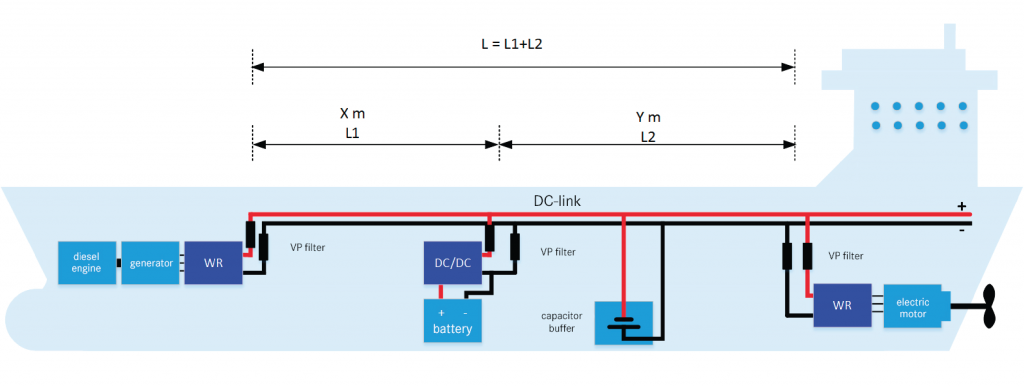
The following description is to draw attention to the possible pitfalls when planning and commissioning an electrically operated drive, for example, in ships or utility vehicles etc. The consumers and power generators are generally connected with each other via a shared DC link. This link can be very large, depending on the application. Conductor lengths range from a few meters to over 100 m.
2 The conductor as a relevant element
The individual components in a DC link interact with each other and thus form systems that are capable of oscillation. This already starts with the purely DC conductor routing that interacts with the input capacities of the inverters. A double voltage conductor for the DC link, for example, has an inductance per unit length as well as a capacitance per unit length in relation to its length. Typical values of double conductors in DC links are 1 μH/m for the inductance per unit length and 100 pF/m for the capacitance per unit length.
3 Parasiticoscillating circuits in the DC circuit
In connection with the inverter capacitance, such a double conductor already forms an LC oscillating circuit due to its inductance. Further components such as inverters, DC/DC converters, generators, motors, and batteries have similar electrical parameters and can form very complex oscillating systems when combined.
- From ARADEX‘s extensive experience: The possible resonant frequencies that can occur here are in ranges that are easily excitable due to the common clock frequencies of inverters (2-16 kHz).
- Undesirable, parasitic oscillating circuits are also found in DC circuits and can be excited by the system related clocking of inverters, DC/DC converters, etc.
This characteristic is shared by all internally clocking inverters and DC/DC converters.
4 More power components mean more interactions
The system becomes considerably more complex when the installation contains several inverters, possibly with different intervals and conductor lengths, as well as with different clock frequencies. Since each component – generator, drive, onboard system, battery, solar cells, etc. – is connected to the DC link with an inverter or DC/ DC converter, the probability of undesirable interactions is high and increases with the number of integrated components. The clock frequency of an inverter can also excite a resonant frequency when it is somewhat close to it, since the resonant curves have a certain width due to damping. Furthermore, resonances are also easily excited by double or half the frequency. As a result of non-linear effects, even sums and differences of inverter clock frequencies can act as exciting interference frequencies. The probability of a resonant excitation in such a complex system is consequently very high.
5 How real is the danger in practice?
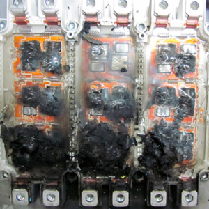
In addition to considerable heating of the current-carrying conductors, this can lead to the destruction of components or danger to life and limb. Standing waves can also occur in the DC link that cause considerable currents, over-voltages, and heating in the case of resonance.
Actual measurements show that when resonant oscillations occur in a DC link, extremely high AC currents can flow, up to the magnitude of the nominal currents. The following illustration shows, for example, a resonant current oscillation in a DC link on an electrically driven ship with an amplitude of approx. +/- 180 A (green curve, green scale, numerical values in A). With a DC link voltage of 600 V, more than 100 kW of power is oscillates uncontrollably in the system.
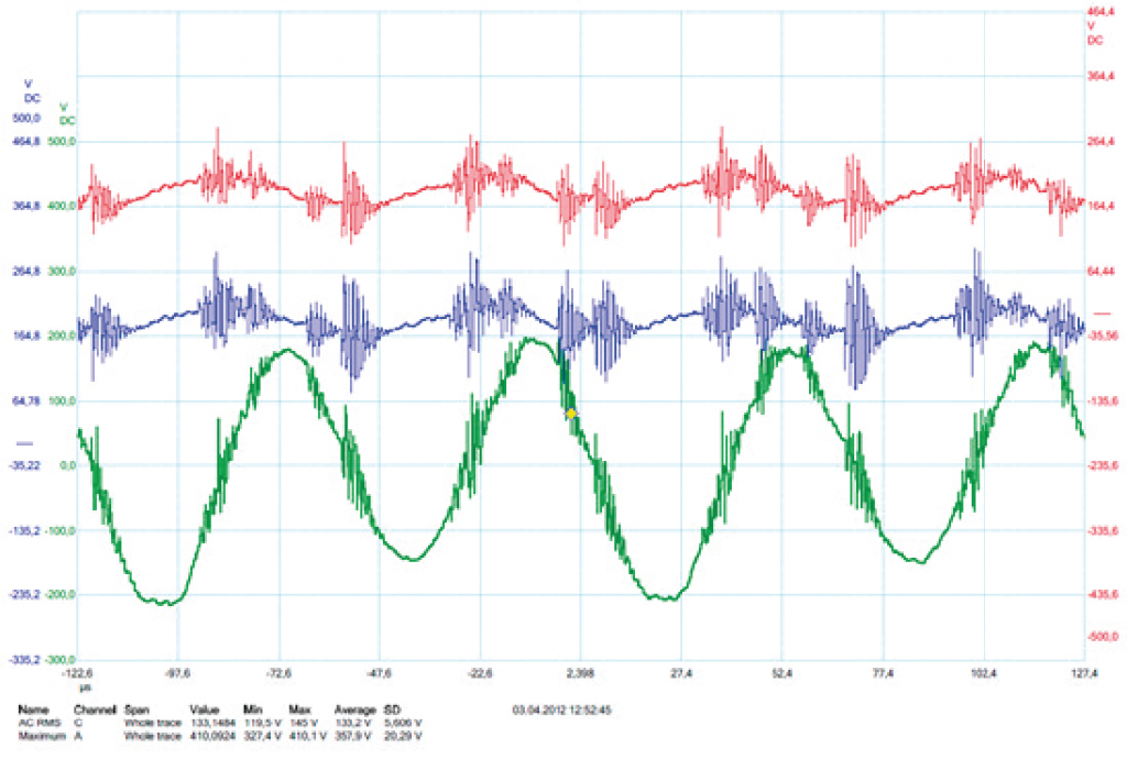
Green curve: current in [A]
6 Possible solutions
6.1 General
In general, we can prevent such undesirable resonant oscillations with the following measures:
- Installation of adapted HF filters that can shift the frequency as well as have a damping effect. However, phase shifts in the current are to be expected here, which can have additional effects.
- Changing the clock frequency of the inverters. Here the possibilities are severely limited because changing the clock frequency also changes many other system characteristics, for example, the possible power rating.
For this purpose, ARADEX offers system engineering based on the respective configuration as well as suitable special filters for the ideal connection of the VP inverter to an overall system.
- Contact us. Our VPEQ series has the right add-ons for the optimum system integration of our VECTOPOWER products.
6.2 Orientation: In what application cases do I have to apply measures for suppressing undesirable oscillations?
There is no generally valid answer to this question. It is always recommended to check for possible undesirable oscillations when commissioning new systems. However, based on theoretical considerations as well as numerous implemented projects of this type, we can give a few suggestions for system configuration.
6.2.1 Applications where undesirable oscillations in the DC link are less likely to be expected:
- A system with only one inverter, which is directly connected to a battery
- New knowledge: several inverters in combination with short cables in a control cabinet and sufficiently high capacity in the DC link.
6.3 Countermeasures
For all applications with several combined inverters that do not have the special features mentioned in 6.2.1, we must assume an oscillation tendency in the DC link, to be safe. The countermeasures are filters that shift the resonant frequencies into less critical ranges and have a damping effect at the same time. ARADEX offers a number of customized filters for this in the VP EQ series. It is usually sufficient to connect one filter before each „+“ connection of the inverters.
6.4 Comparison of AC technology to DC technology
For information purposes only: Comparison with distributed AC systems. Distributed AC systems also have a tendency to oscillate. However, if inverters are connected to chokes or LCL filters, they function just like the special purpose ARADEX DC filters. However, the ARADEX DC filters are more compact, lighter and more economical.